Case Study
Leinfelden-Echterdingen,
Crack inspection of hardened components
Automated crack testing efficiently replaces manual magnetic particle processes.
Steel components in the motor and transmission sector are often inductively hardened to increase the mechanical strength of the surface. Errors in the hardening process can lead to cracks, which must be ruled out for quality and safety reasons. edevis inline testing technology replaced labor-intensive magnetic particle testing at two automotive suppliers and reduced cycle times to a few seconds.
Project Description
Introduction
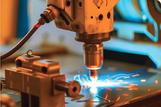
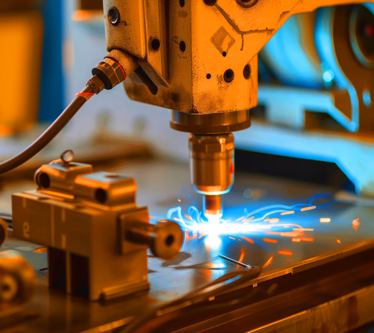
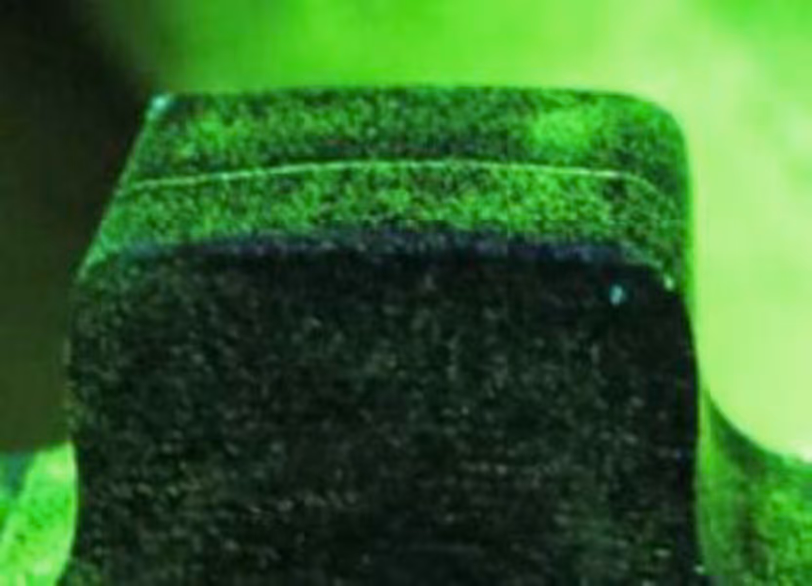
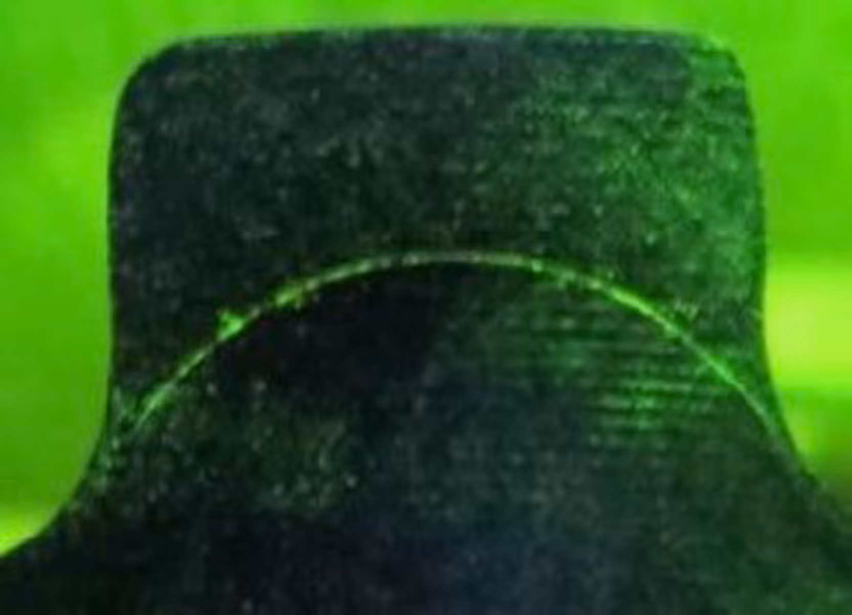
In the induction hardening process, only the areas close to the surface are hardened, not the steel or forged components as a whole. The material properties change abruptly at the transition from hardened to unhardened areas. This causes stresses that can lead to cracks. These can be detected not only reliably but also very quickly using induction thermography.
Application
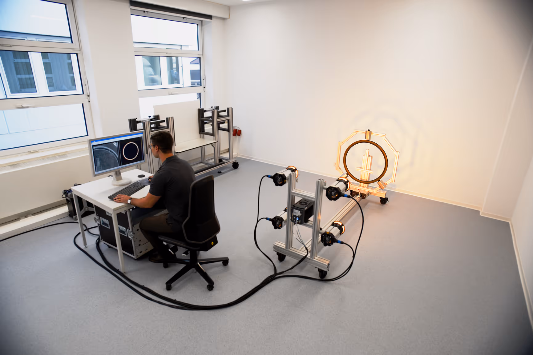
Hardened forged components should be checked for cracks quickly and reliably without contact and without the use of chemical additives. The clients were automotive suppliers for passenger cars and commercial vehicles. One application involved the automated testing of commercial vehicle individual cams from assembled camshafts – in many new engines, camshafts are often no longer forged in one piece, but assembled from individual parts. The other application involved testing passenger car parking lock wheels that are installed in transmissions. These are used in automatic transmissions and, when the selector lever is set to “P” in combination with a locking pawl, lock the transmission and thus prevent the vehicle from rolling away. The application of the parking lock wheel tooth fit test is described in more detail below as an example.
Benefits (for the customer)
In the past, up to 10 inspectors were required to perform magnetic particle testing on the parking lock wheels. This time-consuming manual process has been replaced by inline testing with a cycle time of around 8 seconds.
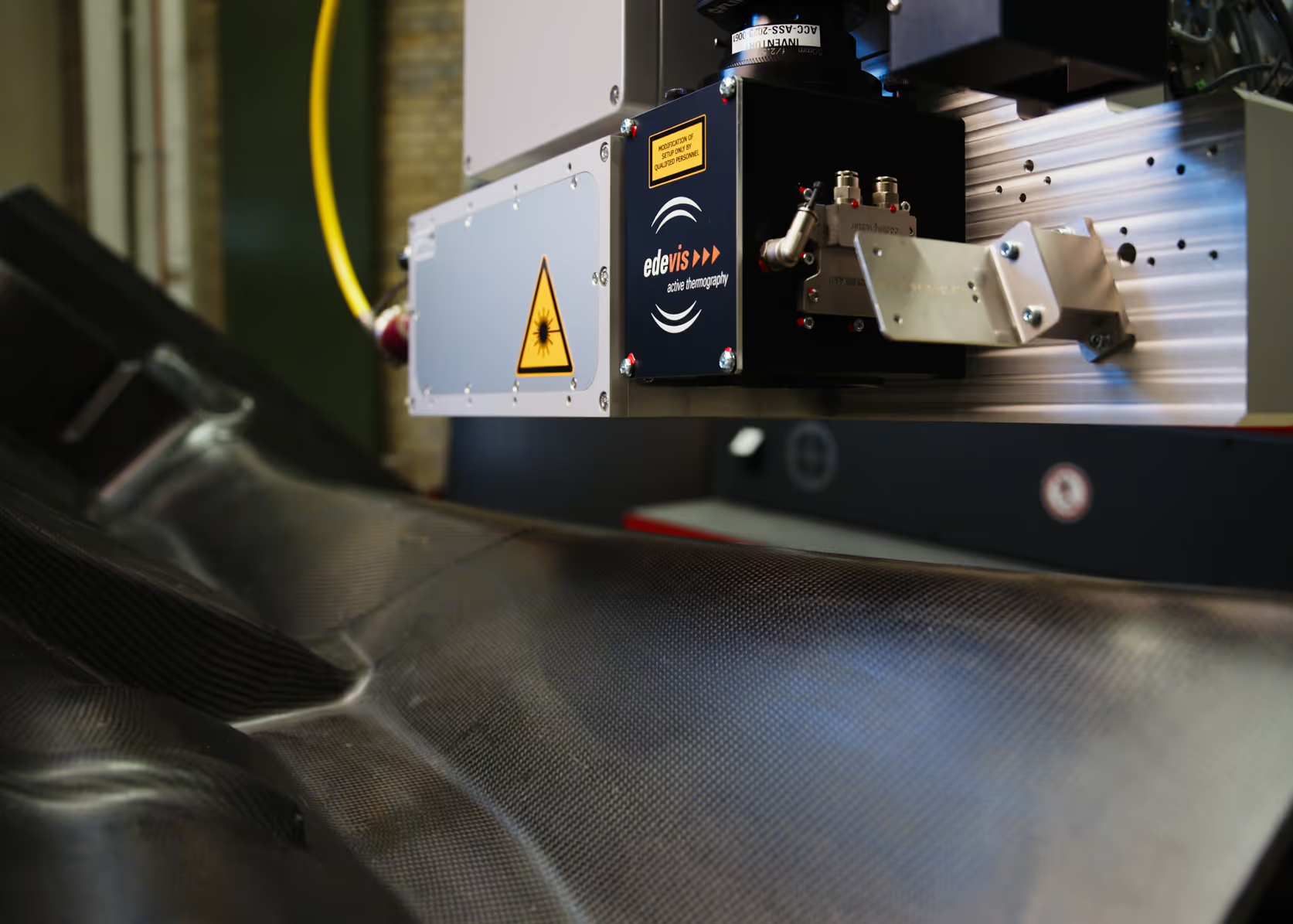
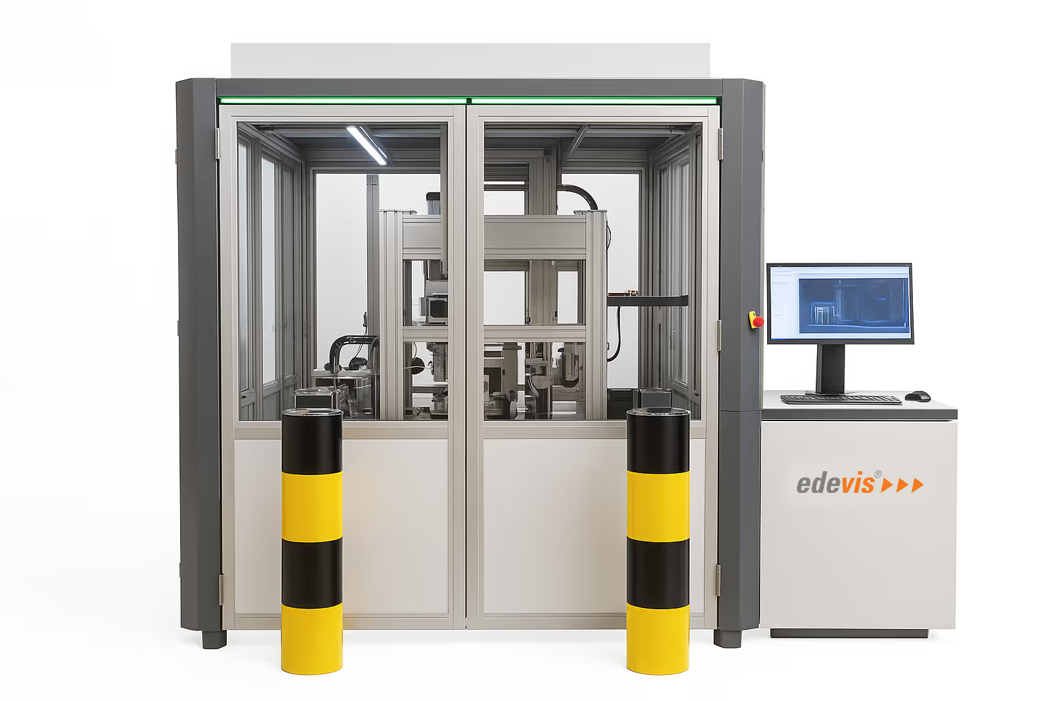
Solution
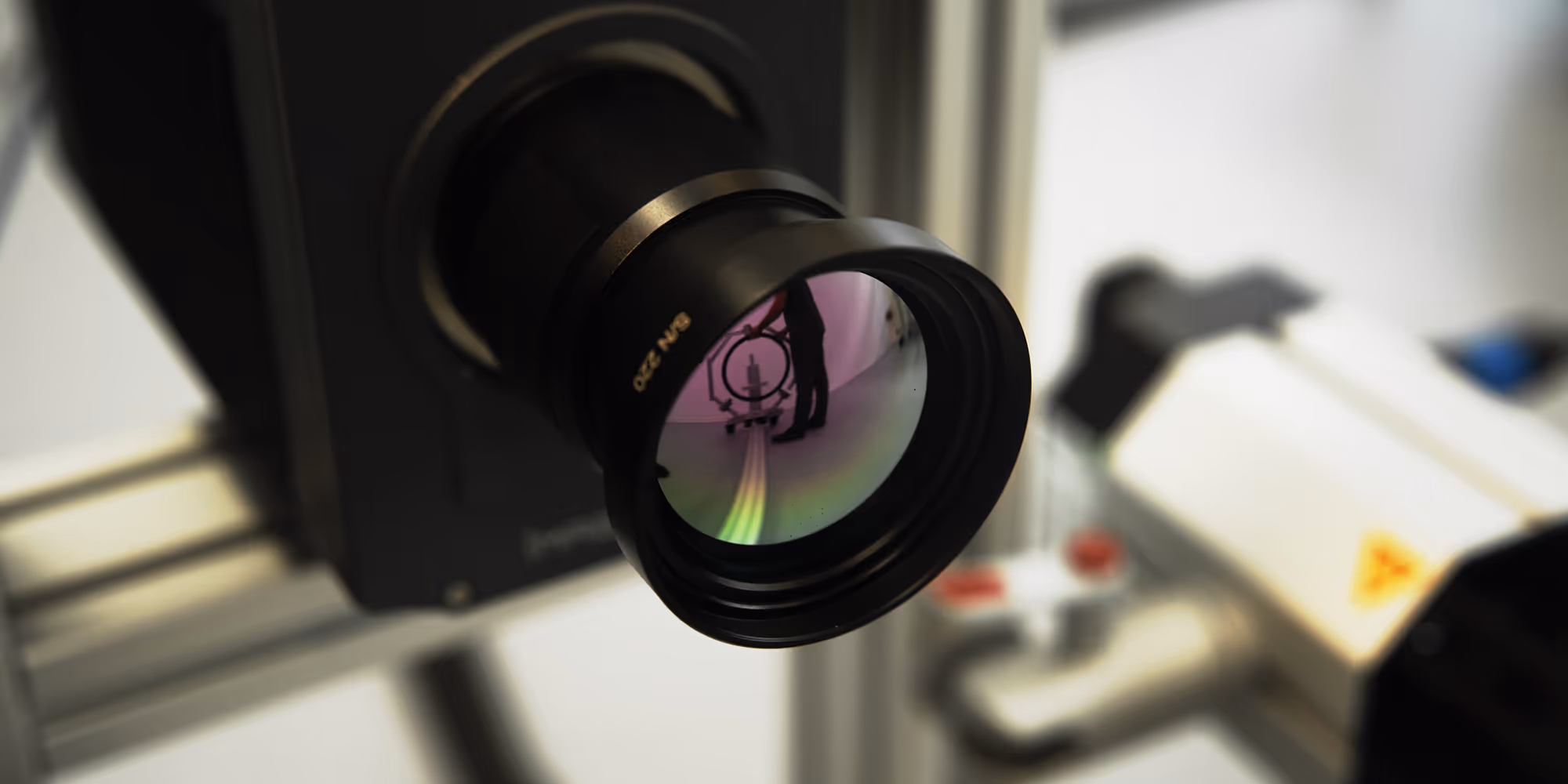
An inline inspection system with induction thermography was used. Thanks to the extremely high inspection speed of one tenth of a second per image, fast cycle times are no problem. Since infrared radiation behaves in the same way as visible light, it is possible to inspect from several sides at once using mirrors. This means that components can be inspected from three sides without having to be repositioned.
Challenge
Since the measurement is carried out using imaging methods, in practice, it is necessary to eliminate some external disturbances in the form of vibrations or reflections. This is solved by recording not just a single image, but a film sequence whose duration is less than a tenth of a second. Using Fourier transformation, you can amplify crack signals and remove influences. When testing hardened components during the manufacturing process, there is another variable: heat. The components are hardened, quenched, stacked and fed to the testing machine between around 800 and 950 degrees Celsius. The last stored part has significantly higher residual heat than the first. For example, a temperature window of between 80 degrees and room temperature was defined for the components during the test. These differences can also be averaged using the method. In other areas, too, it is important to deal with process fluctuations, e.g. due to different batches of components or variations in the pre-process, such as different lubricants, which can be reflected in the result. Dirt, for example, does not occur as part of a laboratory test, and contamination, such as burnt out lubricant residues, cannot be prevented in production. Some of these appear as dark spots on the test results of the gearing surface. The advantage of imaging methods such as this is that, using a suitable image processing strategy and trained comparative images, the testing technology can be used to deal with such deviating process effects.
Implementation
The customers first sent us a few selected test specimens, which we used to conduct a feasibility study in our test lab. This was followed by joint process development, during which requirements and implementation options were coordinated with the customer and the plant manufacturer. This also took place in the on-site production facility. After successful implementation, we provided series start-up support and teach-in with the customer until acceptance = full-service package. However, other implementation processes and forms of cooperation are also possible and can be agreed upon on a case-by-case basis. For this application, semi-skilled operators are sufficient for the testing machine, as the machine inserts the components independently and classifies them as OK or NOK.

FAQ
Our frequently asked questions — answered quickly and easily.