
ITvis
Ultra-fast, non-destructive testing using induction thermography
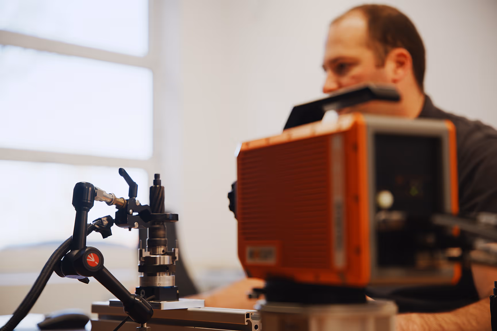
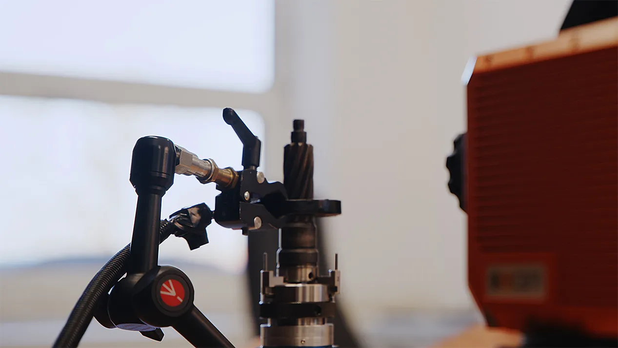
ITvis stands for high-speed crack and weld inspection on metallic components. The systems are based on the principle of contactless induction heating – ideal for inline use, automated processes, and precise material analysis within seconds.
Applications
- Crack inspection on metallic components – fast, precise, and contactless
- Weld seam inspection and detection of welding defects in production and maintenance
- Inspection of soldered and bonded joints for integrity and adhesion defects
- Detection of laps and near-surface structural changes
- Inline testing in series production with extremely short cycle times
- Quality inspection of joints on hybrid or structural components
Advantages of ITvis
- Non-contact and non-destructive
- Objective and reliable results
- In-line capable and automatable
- Very short inspection time
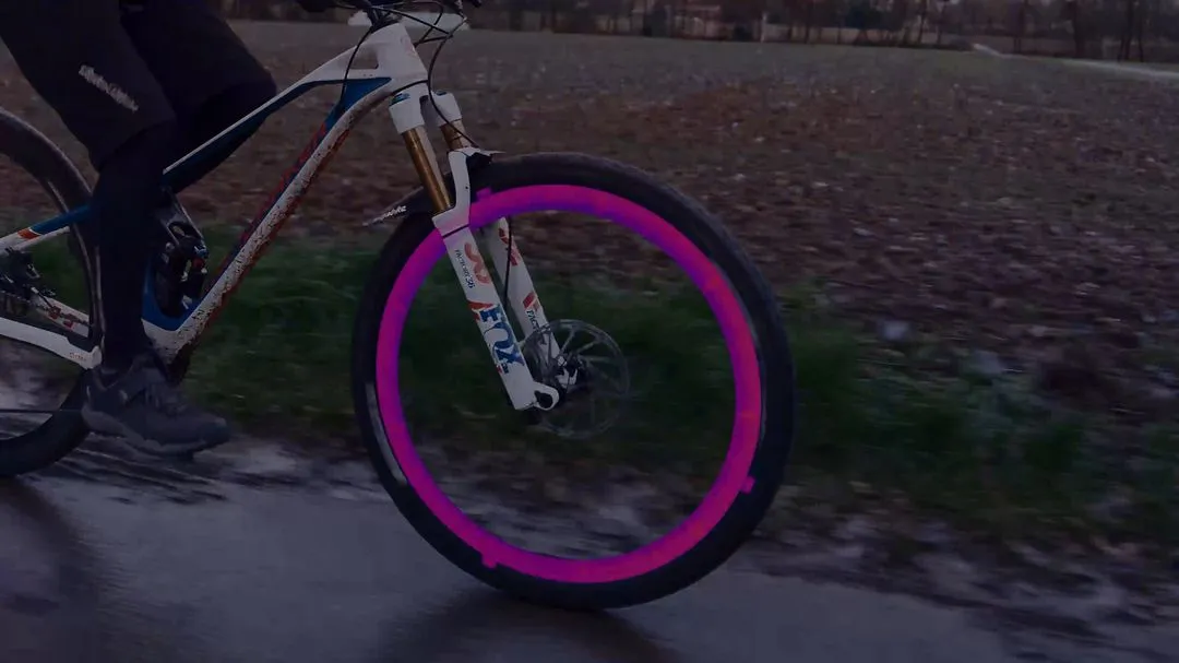
VIS
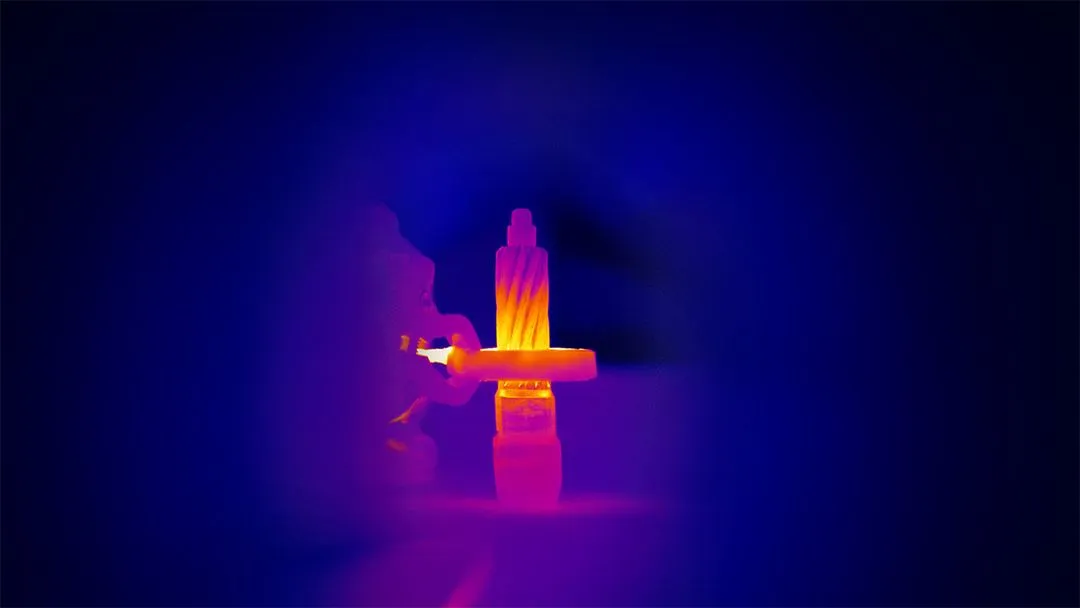
IR
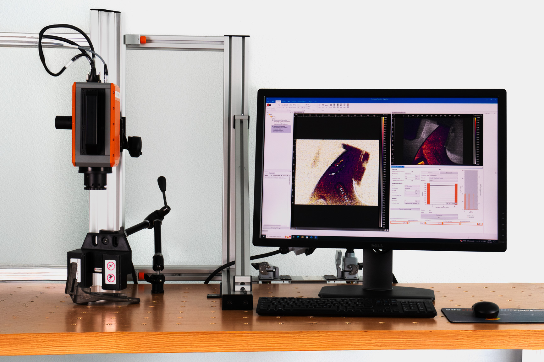
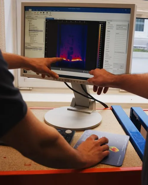
How does inspection with ITvis work?
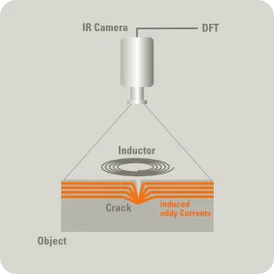
ITvis systems are based on the principle of induction thermography – a contactless, non-destructive testing method for rapid detection of cracks, laps, and irregularities in metallic components. An induced current generates localized heat within the part. Material defects alter the current and heat flow, resulting in characteristic “hot spots” on the surface. These are captured by an infrared camera and analyzed using software.This method is ideal for high-speed crack inspection – especially in automated processes for production and maintenance.
Typical procedure of an ITvis inspection
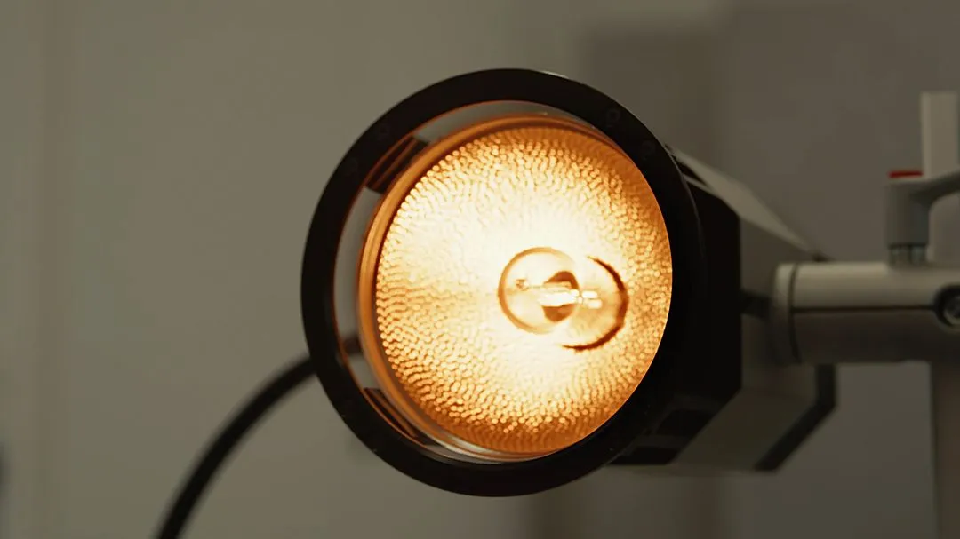
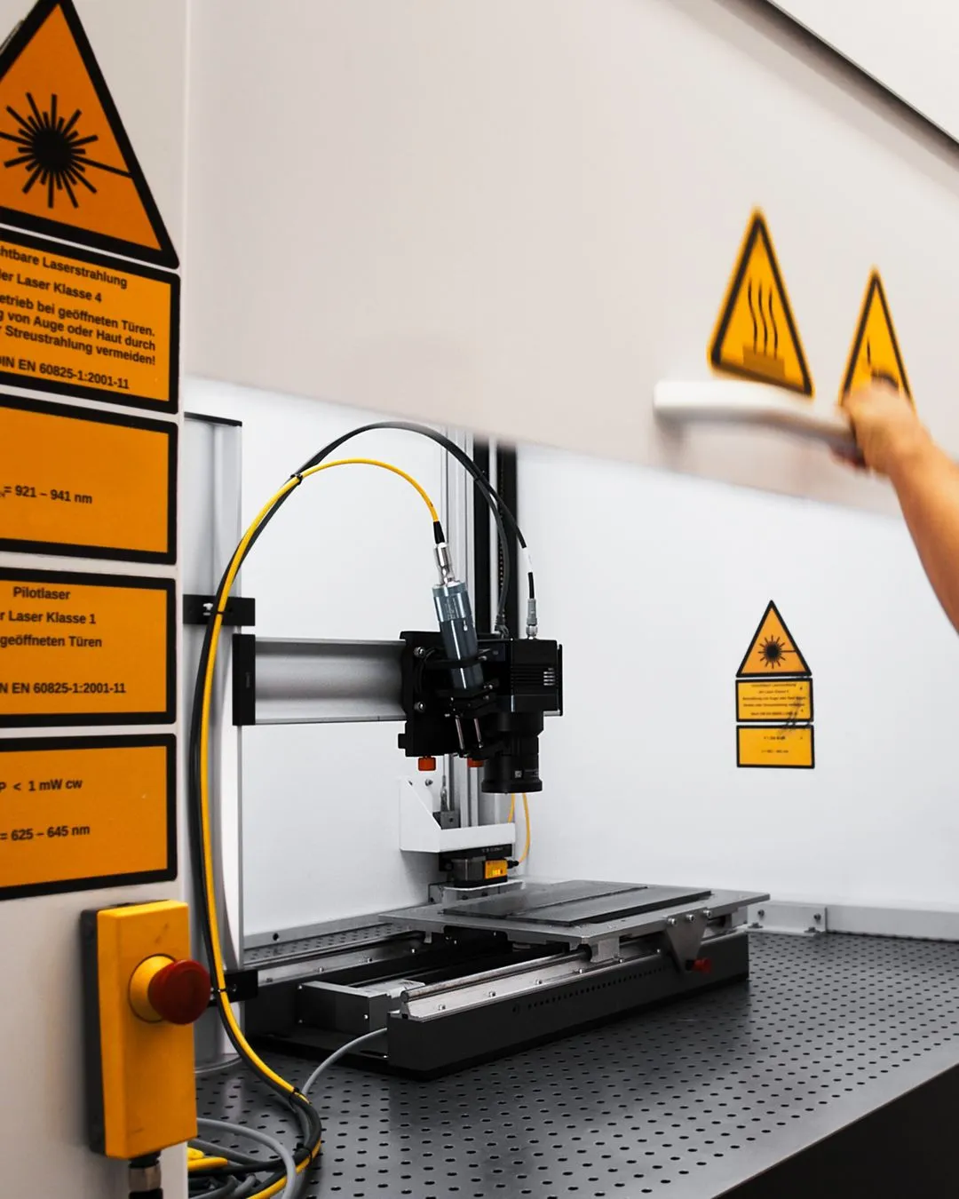
1. Excitation by induction
High-frequency alternating electromagnetic fields generate localized heat within the metallic component.
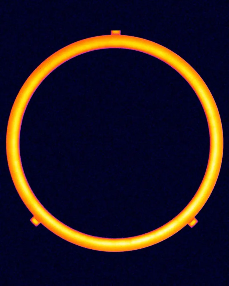
2. Heat propagation & thermal blockage
Defects such as cracks alter the current density distribution → heat accumulates locally → a hot spot is formed.
3. Infrared imaging
An IR camera detects these temperature differences in real time – without contact.
4. Signal processing & analysis
Fourier transformation generates phase images that reveal defects – independent of surface condition or excitation variations.
Specifications
ITvis systems can be divided into two frequency ranges: MHF (Medium High Frequency) and HF (High Frequency).
The key difference lies in the operating frequency – and thus in how deeply the induced current penetrates the material.
MHF systems are suitable for inspecting deeper structures, while HF enables high-resolution detection of near-surface defects.
Choosing the right frequency range directly affects both inspection speed and sensitivity.
MHF (Medium High Frequency)
Frequency range
6 - 60 kHz / 15 - 60 kHz
6 - 60 kHz / 15 - 60 kHz
Cooling
air-cooled
air-cooled
Inspection speed
high
high
Systems
iTvis 3000MHF, ITvis 5000MHF
iTvis 3000MHF, ITvis 5000MHF
Typical application
Crack inspection on thick-walled components, weld seams
Crack inspection on thick-walled components, weld seams
HF (High Frequency)
Frequency range
50 - 450 kHz
50 - 450 kHz
Cooling
water-cooled
water-cooled
Inspection speed
Extremely high, ideal for inline testing
Extremely high, ideal for inline testing
Systems
ITvis 10000 HF
ITvis 10000 HF
Typical application
Microcracks, fine edge cracks, solder seam inspection
Microcracks, fine edge cracks, solder seam inspection
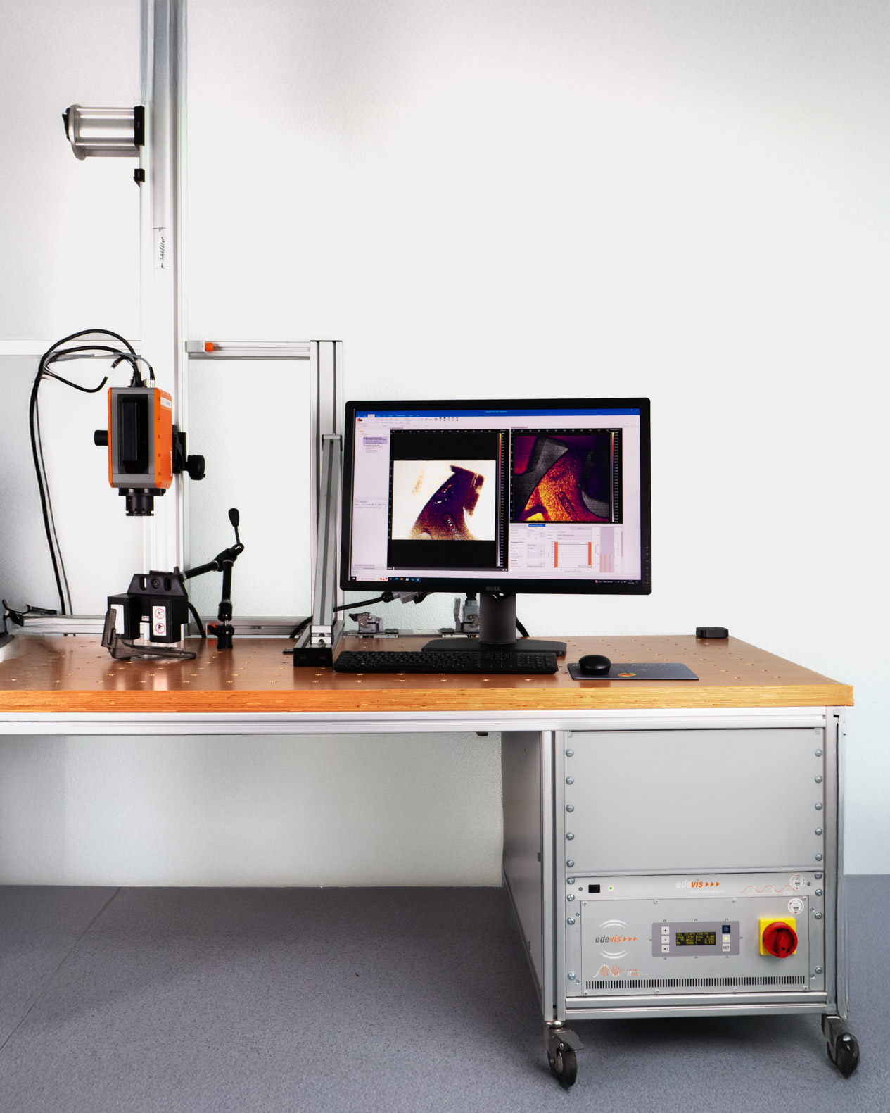
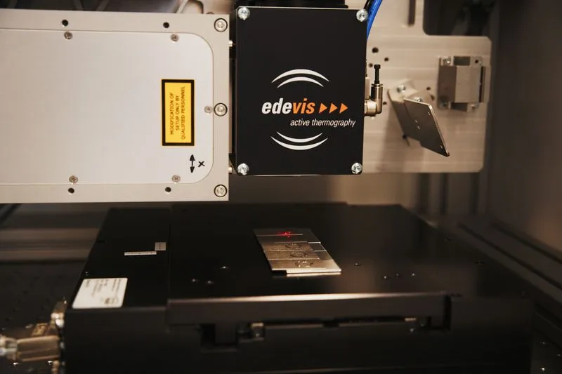
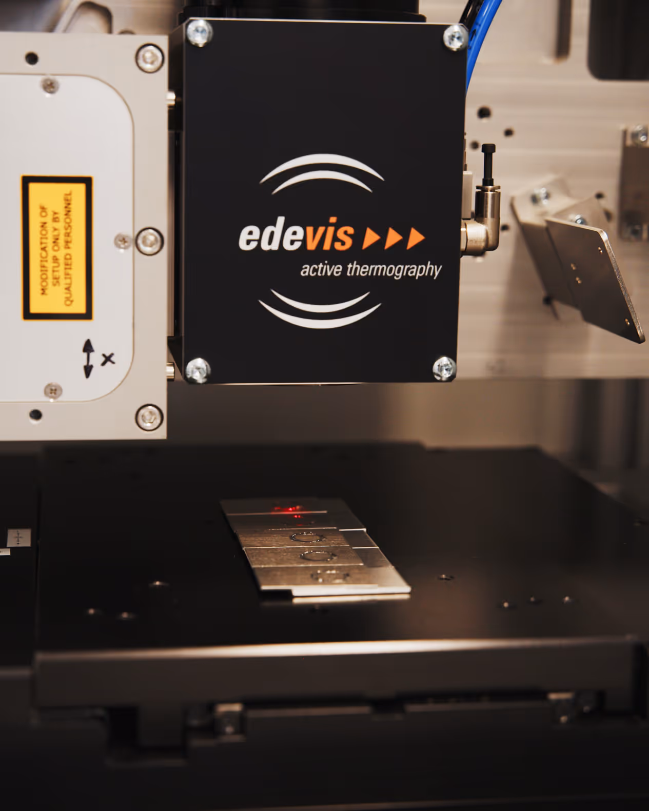
Modular system
ITvis consists of:
- ITvis induction generator
- Software module for device control
- Inductor (to be ordered according to application)
Additionally required:
- IR camera with MWIR or LWIR detector
- ESG signal generator
- edevis DisplayImg software
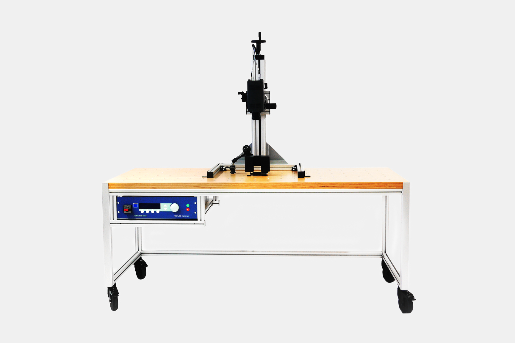
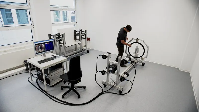
- Test bench/handling system (optional, for automated tests)
The system can be used for both laboratory tests and automated inline setups.
- ITvis induction generator
- Software module for device control
- Inductor (to be ordered according to application)
Additionally required:
- IR camera with MWIR or LWIR detector
- ESG signal generator
- edevis DisplayImg software
- Test bench/handling system (optional, for automated tests)
The system can be used for both laboratory tests and automated inline setups.

Evaluation software:
DisplayImg Professional
- Control of laser unit & camera
- Phase image analysis & Fourier evaluation
- Project management, API integration
- Compatible with all edevis excitation types
DisplayImg Automation
- Flexible modular system
- Active & passive thermography
- Automated data acquisition
- OPC connection & SQL export
- Barcode/DMC scanner


Still unclear whether we can test your product?
In a short initial consultation, we will explain how we can provide you with useful support with thermography — clearly, transparently and without obligation.
FAQ
Our frequently asked questions — answered quickly and easily.
Can I have my product inspected in advance?
For which industries is thermography relevant?
What exactly does edevis offer?
What is the typical course of a project with edevis?
Product inquiries
Message sent!
Oops! Something went wrong while submitting the form.