Case Study
Leinfelden-Echterdingen,
Automated contact pattern inspection
of transmissions in series production with infrared thermography
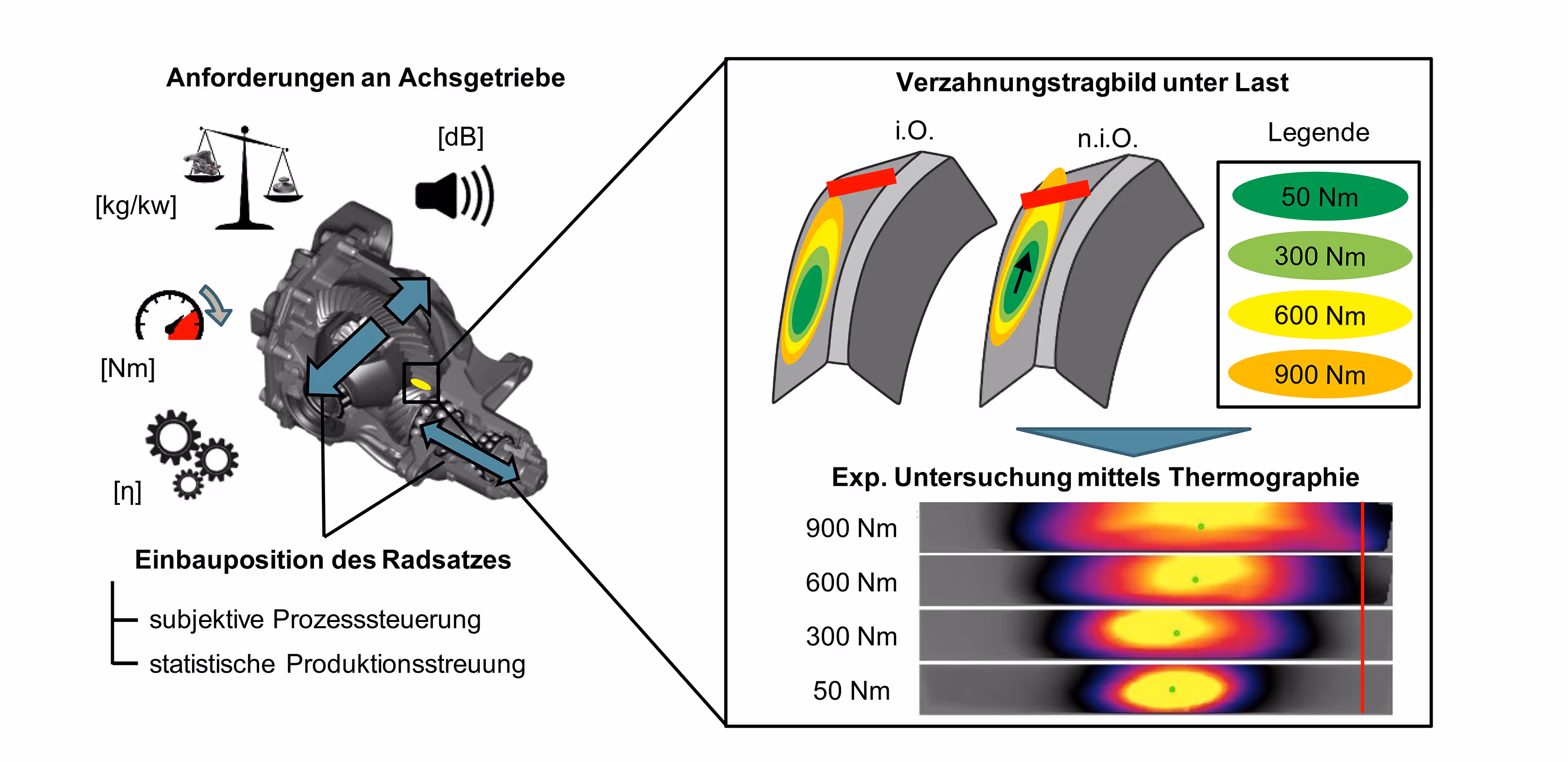
The bearing pattern of gears reveals at which points the force is transmitted when the tooth flanks interlock. If, during the test, the structure deviates too far from the specification of the optimal structure, the transmission is readjusted or sorted out. Conventional testing with ink paste is time-consuming and intensive to clean and only reflects the cumulative impression. The newly developed thermal inline support pattern test from edevis, on the other hand, tests the load structure in the load test bench quickly, without leaving any residue, fully automatically and can individually evaluate each pair of teeth as required.
Project Description
Application
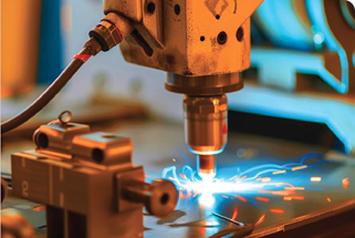
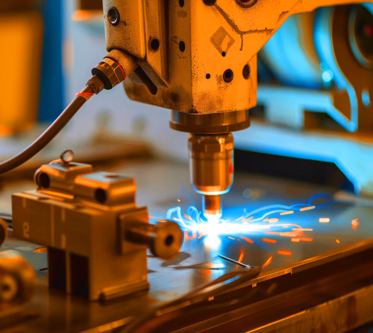
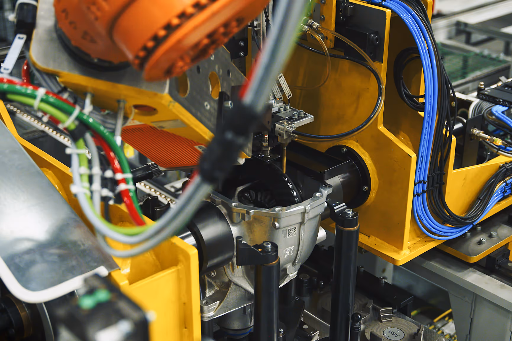
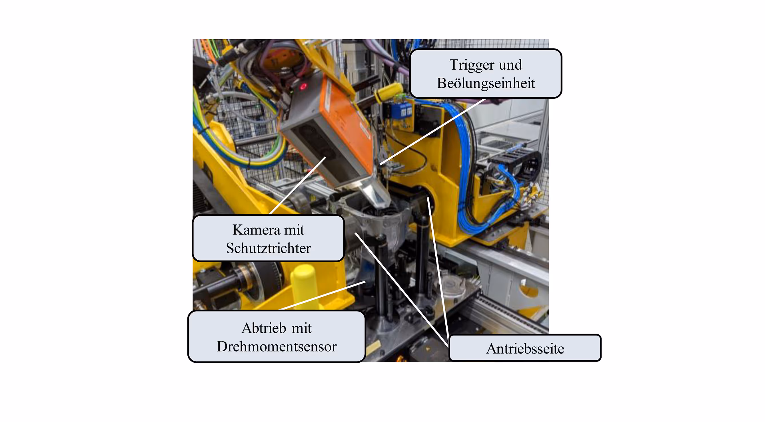
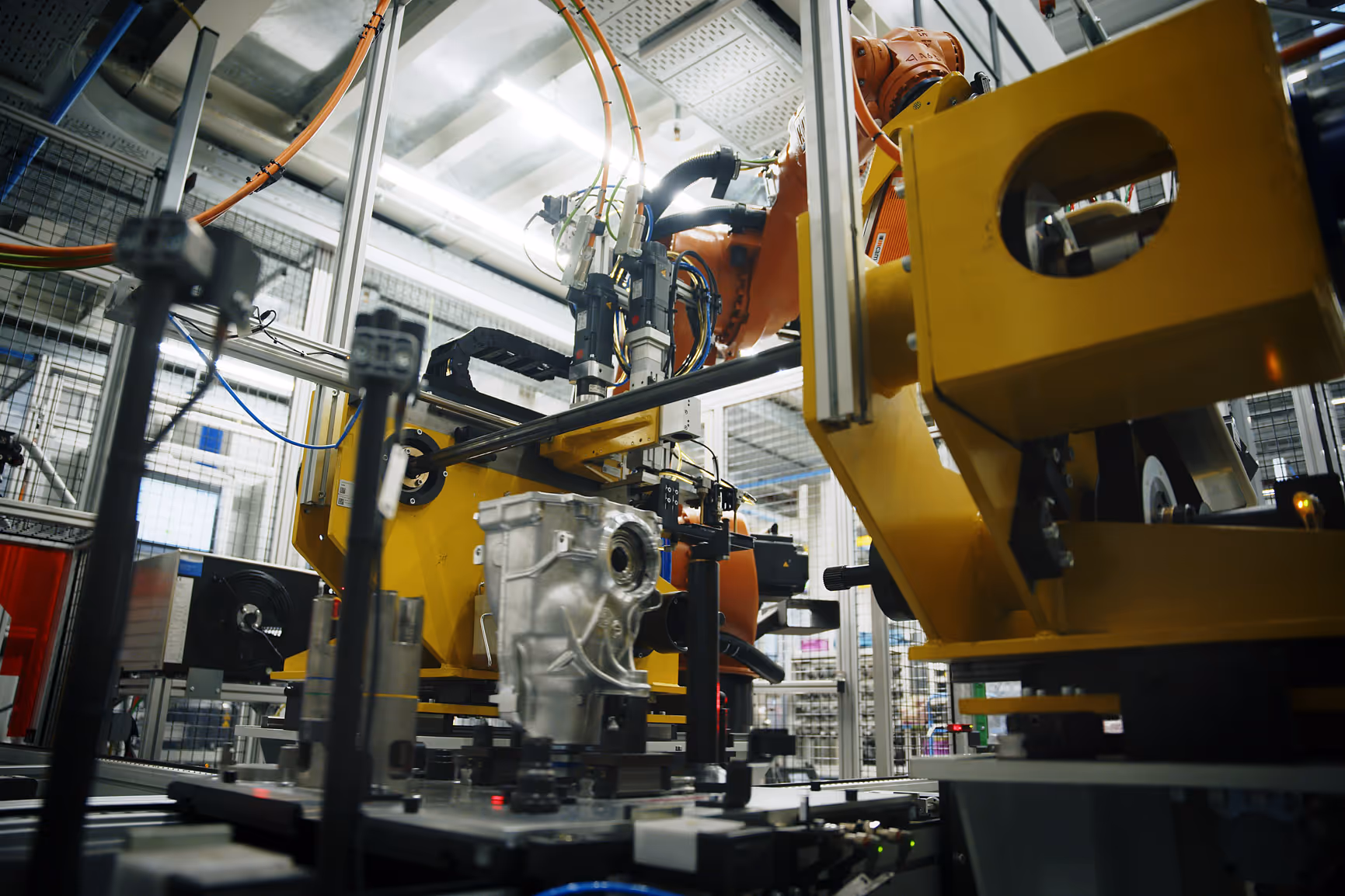
In fully automated transmission manufacturing, the rear-axle gears of a motor vehicle manufacturer are to be subjected to a contact pattern test. In an inline test station, the gears are loaded with a defined torque so that a thermal fingerprint is created between two teeth. With an infrared camera, the frame is visualized and automatically evaluated.
Benefits
The advantages of rationalization through thermographic processes are great. Instead of the previous load-bearing pattern test using ink paste, which requires paint application and subsequent cleaning, infrared thermography can be used to determine the supporting pattern fully automatically in short cycle times and without additives.
Task
The task was to develop and implement testing technology to determine the structural structure. The gears rotate at up to 400 rpm and sharp and repeatable images of each gear tooth must be captured despite the movement. This requires the use of very powerful infrared cameras, which work with relatively short exposure times and fast image sequences. During the test, the transmission had to be turned around five times in order to be able to mathematically cover all possible tooth pairings. The total cycle time, including inserting, turning and measuring, was 28 seconds.
Challenge
The teeth can look very different from gear to gear because they have different shapes and have different (e.g. polished or bonded) surfaces. As with a stroboscope, the camera must capture the tooth at exactly the right time and in the right angle position. Ambient reflections must be ruled out.
Solution
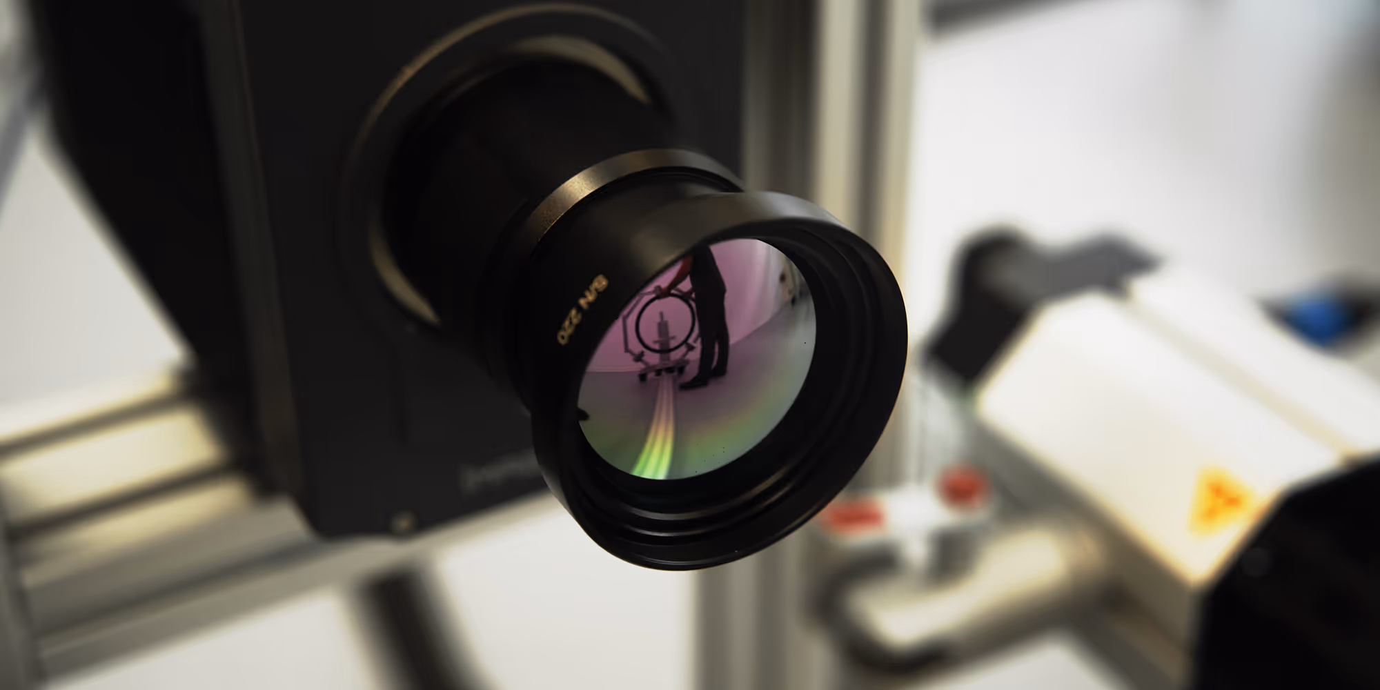
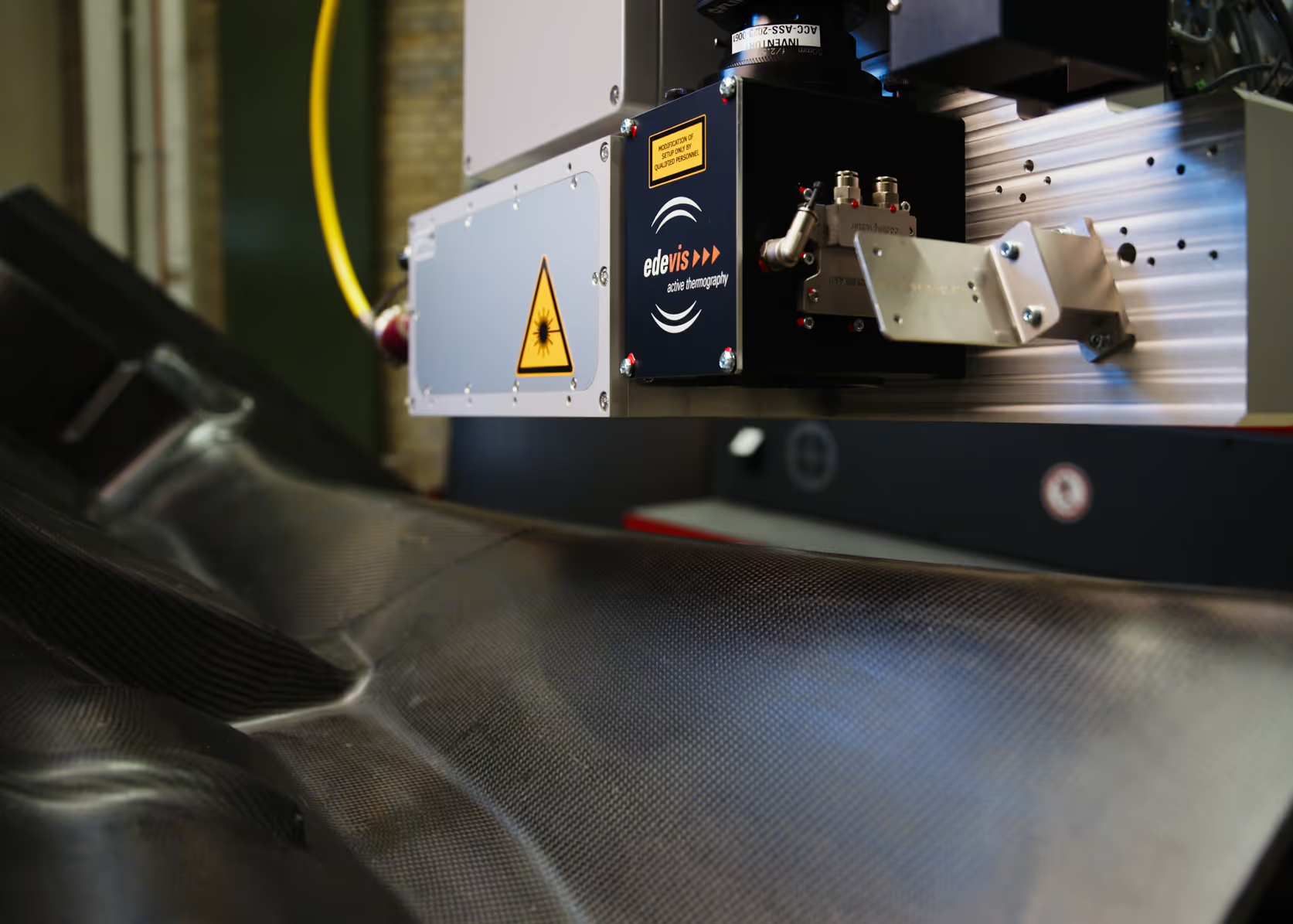
In order to be able to correctly evaluate all tooth combinations, several images are taken of each tooth. By changing the direction of rotation, it was ensured that the teeth can be examined on both the tensile and thrust flanks. The images were taken with a Stirling-cooled infrared camera with large, light-sensitive pixels. The torque applied to the test bench was transmitted to the camera in real time and thus made it possible to calculate differential images without and with load.
Machine learning
The decisive success factor of the project was “machine learning,” which allows the testing software to work intelligently and independently sort out faulty parts. The first step is to teach the software to segment the tooth of a transmission and to uniquely identify it during the run. With an adjustable trigger delay, the infrared camera made it possible to select the right time at which the teeth are optimally detected. The test software learns which tooth profile is still within the tolerance range of the prescribed support structure and which is not through a teach-in process. First, transmission patterns are read in as master images, which serve as a reference for the load pattern test. The tolerance range, what a measured support structure should look like and how far it may deviate from the target state, is parametrically defined by the customer. After the training process has been completed, the bearing pattern deviations are identified automatically and reliably.

Implementation
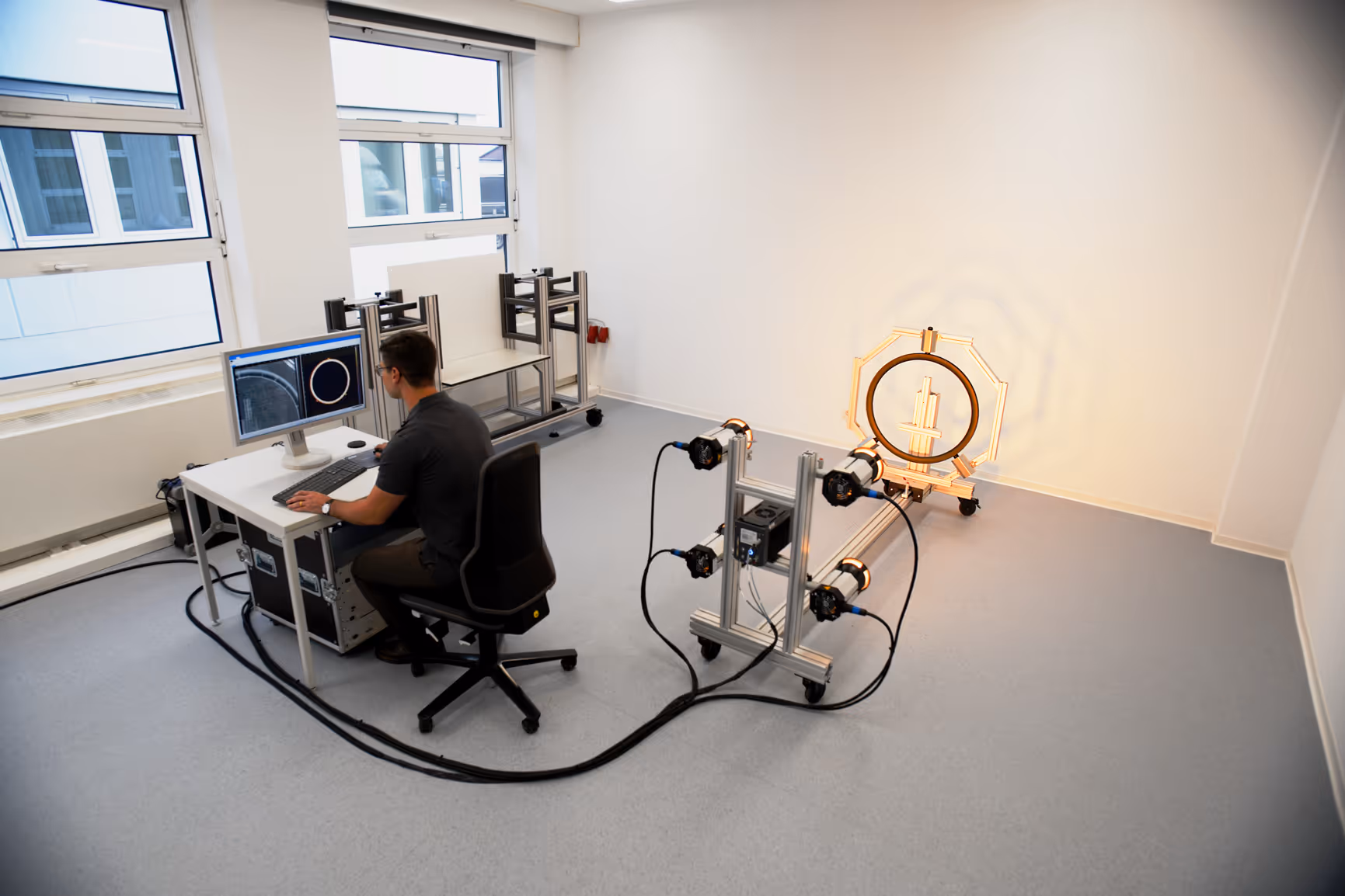
At edevis, the project planning could not be carried out completely in its own test laboratory, as the transmissions can only be meaningfully tested under load. However, this hurdle was partially overcome by experience from previous projects with major automotive manufacturers. Parts of the order were developed in a laboratory situation and later verified under load, other parts directly at the customer's site. The test bench was developed in close cooperation with the customer and the plant manufacturer.
FAQ
Our frequently asked questions — answered quickly and easily.